


Product Details
Our Cellular Tower Survey Reports help mitigate the hassles with determining what Cellular Carriers are available at a specific location, their headings, distance, elevation and other pertinent information.
The report can assist in:
- Determining the closest towers to a location for selecting the best cellular tower and carrier
- Selecting an antenna that is compatible with the distance, heights and terrain
- Determining if the height of an antenna mask/tower will obtain Line of Sight with a cellular tower
- Knowing the exact heading to use for aiming a directional antenna
The Reports are offered in two levels of service:
- PDF with Satellite Images
- PDF with Satellite Images and KMZ Google Earth file
Disclaimer: Network carriers are constantly constructing and modifying towers to accommodate new services, frequencies and bands. All efforts are made to ensure the accuracy of our survey reports are based on the most current available data.
Survey Reports are prepared and delivered via email within two business days. Please direct all survey inquiries to: surveys@thewirelesshaven.com
PDF REPORT
Our PDF format report contains general information on each tower to include:
- Carrier
- Distance in Miles from the users location
- Heading in Degrees from the users location
- Latitude
- Longitude
- Elevation at Sea Level
- Tower Height
- Line of Sight (with the Tower)
- Type of Obstructions (if any)
The information is conveniently compiled on the first page of the report.
EXAMPLE OF THREE TOWER PDF REPORT--SPRINT, AT&T AND VERIZON

PDF REPORT'S SATELLITE IMAGES
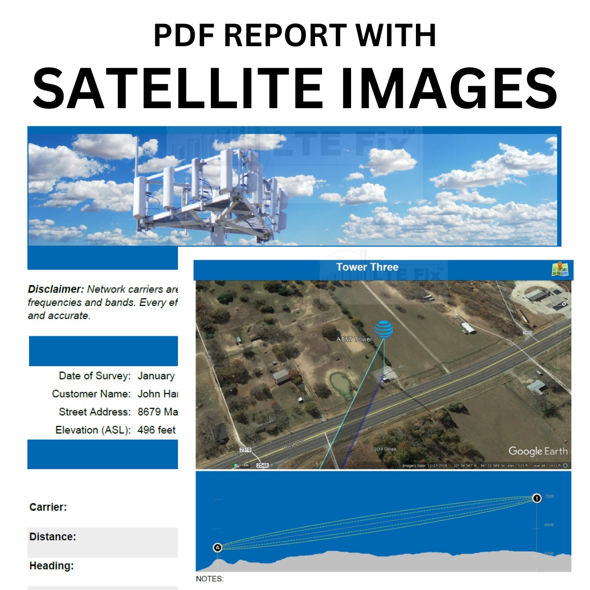
The report also include satellite images for a better visualization of the towers location in reference to a particular location.
The images included is this report are:
- General Overview of all towers contained in a report
- User's Location Antenna ("A") and Cellular Tower ("T") elevation and topology chart with Fresnel zone for each tower
- Each Tower overview (top right) contains a Google Map icon link that will zoom in on that particular tower
An example of these images based on the PDF three tower survey above are shown below:
GENERAL FULL OVERVIEW

TOWER ONE OVERVIEW AND ELEVATION TOPOLOGY CHART

MAPPING ICON

Clicking on the Mapping Icon on the top right of a Tower will open Google Maps and zoom into the tower's location (Sprint, in this example).
TOWER TWO OVERVIEW AND ELEVATION TOPOLOGY CHART

TOWER THREE OVERVIEW AND ELEVATION TOPOLOGY CHART

PDF REPORT WITH SATELLITE IMAGES AND KMZ GOOGLE EARTH FILE
This type of report includes the above PDF with satellite images along with a KMZ file for Google Earth. The quick video below will help to understand the value in this type of report.
https://www.youtube.com/watch?v=zs8uwhgpRs8
Additional Information
Line of Sight
When the Survey Report is prepared, the path between the customer’s location and cellular tower is visually examined by the preparer. The path is determined by the height of the customer’s antenna (as provided) and the height of the cellular tower.
The actual location that a carrier’s antenna is installed on a tower--in relation to the overall height of the tower—can impact a path’s elevation over obstacles. This may be further compounded when more than one carrier’s antenna is installed on a single tower.
When a report indicates an obstacle in the path, a brief explanation of the obstacle is provided. Knowing the type of obstacle will better assist in selecting an appropriate antenna system.
Magnetic North
The majority of compasses do not point to the North Pole. They point in the direction of magnetic North, a spot in the Arctic that is near to (but not the same as) the North Pole.
A Survey Report is prepared using Magnetic North headings which may, in certain locations, require factoring in a magnetic variance. This will help assure its accuracy when the headings are used to aim directional antennas.
Read more and obtain your location HERE.
Learn more about True North HERE
Example of Magnetic Declination Chart


